Are programmers allowed to hack hardware? Analog hardware, in particular? Well, I did it anyway.
Rogers Cable is cutting back its analog channels. This is very annoying, and one of these days, I may cancel my Rogers subscription altogether because of this.
In the meantime, however, I am dealing with a more immediate problem: my desktop workstation and its tuner card. For the past 20 years or so, I have been watching TV in a window while I work, often CNN, just running quietly in the background. My current workstation has a dual tuner card, which allows me to view one program while it records another.
Trouble is, the card only has one antenna input. Why is it a problem?
It's because the cheap cable decoders that Rogers provides for free only have antenna outputs. So even if I used two Rogers decoders at the same time, I could not connect both to my tuner card at the same time:

One possible solution presents itself as the same tuner card does have dual composite video inputs. Unfortunately, the Rogers decoders do not have composite video outputs:

I was certain, however, that there had to be a way to get the composite video and audio signals out of the decoders somehow. After all, the RF modulator requires these as inputs, unless the design of the device is horrendously non-standard, which I considered unlikely.
So I decided to risk Rogers's wrath (or more likely, I risked having to pay $25 or $40 or whatever Rogers charges for a damaged device) and took one apart, starting to poke around in it with my oscilloscope. Sure enough, I found the composite video signal eventually. And when I connected it to the composite video input of my computer's tuner card, there was a nice, clear picture.
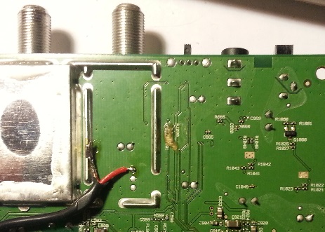
But no sound. Not yet anyway. I had to find the sound signal in the device, too. This took a lot more poking around with the aforementioned oscilloscope, but I found it eventually.
Or rather: I found the multiplexed stereo audio signal. That is, the sum of the left and right channels (and their difference, transposed in frequency), not the demultiplexed left and right channels. I.e., one wire, not two.
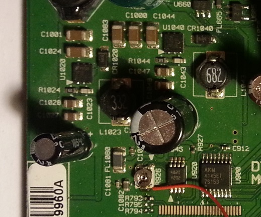
I could have stopped right there and just accepted the fact that from now on, I'd be listening to television audio in mono. Who cares. But I was more ambitious. Besides, the audio volume was a little too low anyway.
So I set out to design a circuit that would decode and amplify the audio. I obviously wasn't planning to design a stereo demultiplexer from scratch; that's what chips are for. Rather, I was looking for a chip that would do the job, preferably one with a minimum number of parts, and one that could use the 5VDC supply voltage that is available in this decoder.
I found what I was looking for in the form of the TDA7230, a low voltage stereo demultiplexer chip (most other demultiplexers require 12VDC, obviously designed for automotive applications.)
This chip also has an audio amplifier built in, which I did not use. I did, however, add a one-transistor preamplifier stage to boost the audio signal a little.
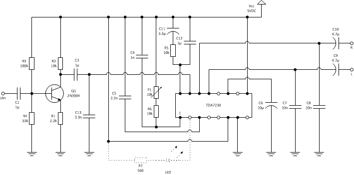
I built a breadboard, wrapping-wire test version of this circuit, and it worked, more or less... sometimes I got terrible distortion, but it was intermittent, so I attributed it to some bad soldering. I was ready to turn my design into "production".
To do so, I did something I never did before: I designed a printed circuit board (PCB) and sent it to a company that manufactures PCB prototypes. For the design, I used ExpressPCB, an excellent little software package, provided for free by a manufacturer of prototype PCBs.
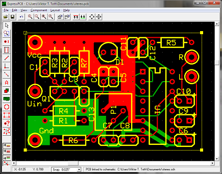
However, I am ashamed to admit that I did not actually use their services for the boards, as I found a substantially cheaper alternative in the form of a company named Futurlec. For the grand total of less than 40 US dollars, I was able to order a set of four PCBs (I didn't pay extra for solder masks or silk screening.) It took a while for them to be delivered (just over a month, in fact) but today, they arrived, straight from Singapore. I actually received nine boards (thank you). They were very nicely done, exactly according to specifications.
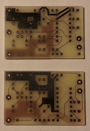
So I set out with my soldering iron and populated one of these boards earlier this afternoon. I wasn't sure what to expect... it's not like I routinely design analog circuits or PCBs. Nonetheless I finished in no time and I had a nice, completed board, ready to be hooked up to the decoder:
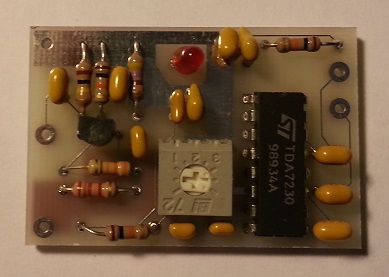
And it worked! Right on the first try. I didn't even have to adjust the trimming potentiometer that controls the detection of the stereo signal.
Needless to say, I feel unduly proud tonight. I have two more decoders to hack, but now that I know that my design works as it is supposed to, I don't expect any trouble.


